|
microscribe
overview
precautions
set-up
unix
windows
getting data
unix
windows
|
GENERAL INFORMATION
The MicroScribe-3D is a tool used to digitize three-dimensional points.
Simply, it translates positional information into X,Y,Z coordinates (i.e.
points) based on a defined origin. The points can then be used in any software
program such as spreadsheet programs or CAD packages.
Currently, the points will mainly be used in Pro/ENGINEER. These points
can be converted into Datum Points for use in creating Datum Curves, which
can be used to create surface or solid geometry. There are three primary
uses for the digitizer:
-
Two-Dimensional Data Transfer: Convert Mylar or drawings into Datum
Curves
-
Reverse Engineering: Create a part from surface information
-
On-Aircraft Component Placement: Determine aircraft positional information
GETTING STARTED
Component Information
To get the most from the MicroScribe, please take a few moments to get
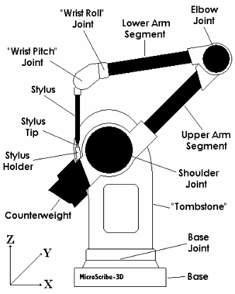
familiar with the principal components. Below is a diagram (Figure
1.0) of the parts and their function:

|

|
|
Figure 1.0
|
-
Base:
-
Foundation of MicroScribe, which remains stationary during use. All input
and output connections are located on the base as well as the green Power
Indicator and on/off switch.
-
Power Indicator:
-
Green light indicating that power is available to unit and it is turned
on.
-
Counterweight:
-
Weight to offset the weight of the arm to afford ease of movement and balanced
positioning.
-
Digitizing Arm:
-
Single-jointed arm that allows the stylus to be positioned nearly anywhere
within the radius of the arm.
-
Stylus:
-
The portion of the arm where the MicroScribe reads positional information.
-
Stylus Holder:
-
Place where stylus is to be stored when not in use and on start-up.
|

